For the most part, it is assembled, only things remaining are to add the table surface (it'll not be a rotary table or anything, though adding that is an option later), and a pair of switches onto the Z-axis.
Software is what's currently holding me back, I'm in the process of modifying the modification of the reprap code located here on google code to handle having two controllers on i2c. I may go through later and make it compatible with the default one, but for now, I've managed to hack it up enough, it's broken most of it.
Also, one important thing to do is to change the i2c bus to be 400kbps, which translates to a byte about every 20 microseconds, vs about 80 by default. (Assuming my arithmetic is right, and it's 4 am. ) This can be done via a #define (
#define TWI_FREQ_400 400000L) in the header/top, and via setting the proper register via: TWBR = ((F_CPU / TWI_FREQ_400) - 16) / 2; following Wire.begin() in your code. I checked the 328 data sheet, and unfortunately that's the max it supports.
Deficiencies have been noted. Wood for example seems to have a problem warping more than I'm used to. Granted, I last worked on wood about 15 years ago as a kid, for more than just carving. In that time, apparently the regulations have changed on how much wood must be dried, so that the percent is higher from 15% to 19%, and changed from exiting the sawmill, to when it is installed, meaning lumber now days has much less drying than it used to, and tends to warp more. (Apparently that warping is supposed to add strength to lumber if it dries while installed in a wall. Good for that, sucks for me though!)
Sunday, October 10, 2010
Thursday, September 9, 2010
Progress

I haven't posted nearly as often as I planned to, but I have been working on it. I'll probably describe what I figured on design, and problems when I get time. So far I've solved the motor to shaft transfer problem, by modifying someone else's solution, which is probably stronger than theirs, as well as some support problems, which are nearly solved (I ran out of screws before I finished the full x/y assembly today.)
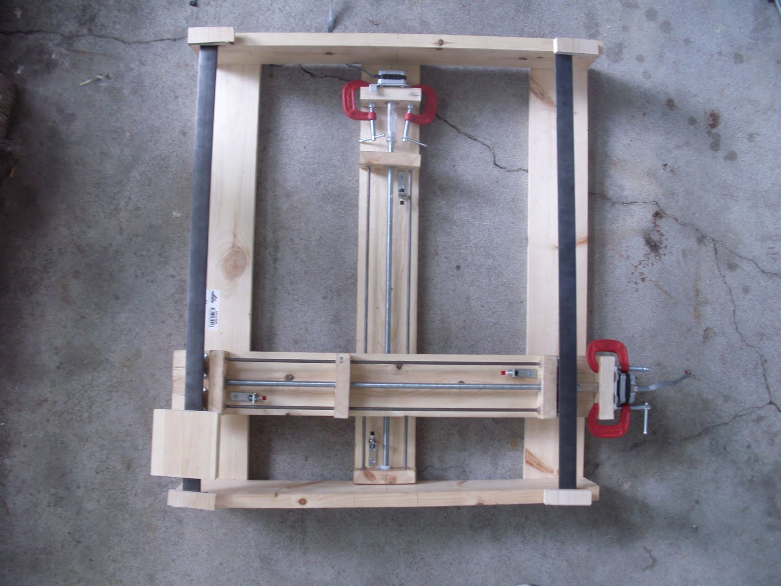
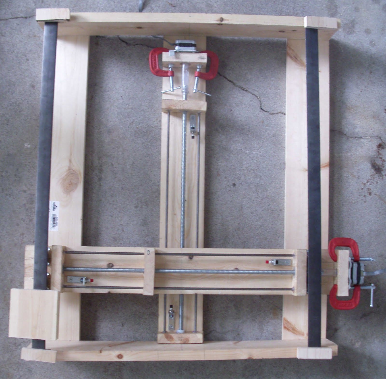 Have a picture of the x/y assembly! It is upside down, and the rails aren't attached yet. You can see some of the odd things I've used, such as the mini clamps to secure the motors, and the vinyl motor to shaft connectors. The block in the lower left was just sitting there to hold the rail down, because the concrete was uneven. The limit switches are in their brackets (easily removable), but I have to adjust the brackets some: the ones in the x/upper, but lower in the picture are too tall, given a mistake I made, so I have to cut the tops off, or grind the top hole out in the L-bracket. (It's just a *tiny* bit too small as it came.) You can also see most of that in the little picture up at the right.
Positioning-
 For Stepper motor controlled axis, you need to have some sort of sensor to tell when you've gone too far, and to figure out where you are.
There two options that seem somewhat practical, there are also some solutions like laser positioning, which seems expensive, complicated and impractical:
1) Rotary encoders, which don't completely show you where you are (I don't think), but they also let you know if you didn't step, because the motor stalled. (A possibility which can burn out chips.) These generally are used on conventional motors, not steppers, but can be to make sure that it steps on better equipment.
2) Limit switches, which tell you where the limits of motion are, and combined with a stepper, assuming it doesn't stall should tell you the position. Also much cheaper. Ideally, these should have very little resistance.
 I opted for Limit switches, though mine don't have quite the limited resistance that one would like. My solution was probably a bit unconventional, but what's new. It's probably what you get when you have someone with no formal training in any circuitry, woodworking, machining, and little formal programming training. In fact, this whole project has that fun of learning while I go. (That fun can also be very frustrating.) To calibrate exactly where one is, it has the problem of having to go to the edge to set the position. I plan on storing the position when it's turned off into the eeprom.
 My solution was to take some L-brackets (Basically pieces of metal bent into 90 degrees, with 4 holes for screws.) and then put some momentary switches from radioshack into it. Unfortunately, the holes in the L-brackets were just a bit too small. Well, that was solved via an application of remel grinding them out a bit. It's not absolutely perfect, as due to my mistake on the x-axis of putting the middle bit upside down, the 1-1/2 inch ones are just a bit too tall, so I'm going to have to cut them down, or Dremel out and use the top hole on the perpendicular unscrewed part. Cutting it will be easier, so that's what I'll do. This may not be the best solution, as the switch may not trigger at the same place every time, due to more resistance than others. Also, it might be better to go with normally closed switches instead of the normally open ones I got, so that it will cut out if a connection is broken, or anything else fails.
Thursday, September 2, 2010
Side project: LED array
This is a minor side project I decided to build with the help of my niece and nephew, to show them something nifty. Motors that aren't that fast, aren't that interesting to them, on the other hand, lights are. Have a video:
This is the Duemilanove hooked up to a breadboard, on pins 1-5, and 8-13 to form a 2x5 array of LEDs, each LED is connected to ground via a 1k resistor to limit the current to about 5 mA so as to not burn the LEDs out. The reason the one in the upper left comes on is that I hit the reset in the middle of it (which is too dark to see). The software I wrote is potentially more general purpose than that, however, it is unfortunate that the Duemilanove has at most 19 (14 digital + 5 analog) that can be used for directly driving the LEDs, so at best if you want an even array, you could get a 4x4 array, or a 3x5 array, using this technique. (And I ran out of loose 1k resistors) I designed an i2c controlled 4x8 using eagle, as I finally figured out most of it. Unfortunately, to get it made it'd cost at least $20 for the chips and PCB. Maybe once the main project of a CnC machine is done it'll have enough resolution to accurately cut PCBs. (It should have a *theoretical* X and Y resolution of 8 micrometers, and a Z of 33 micrometers. I don't think it'll be quite that precise, on the first one, due to the construction method.)
After doing that, I noticed a new thing at Adafruit, the 'LoL Shield' which is an LED array using something I was unaware of until today of Charlieplexing, using multiple inputs and the fact that LEDs are diodes to drive the array. Pretty cool hack, and it seems very similar to what my library uses for animation (and let's face it, what anyone would use). I've got a whole bunch of LEDs I got cheaply off ebay, so if I can get just a PCB, it'd be cool, and I'd probably have the only amber one. Direct link to the maker's commentary on design: Part 1 and Part 2. Always seems to be the case that you find someone has done something a lot cooler after you make something.
Wednesday, July 28, 2010
Materials-The electronics
As noted in the initial post, I already have some (most) of the electronics required. First of all, some basic ideas of how the project is going to be built.
First of all, this is going to be a three dimensional device, and the cutting head will be able to move on at least 3 axis. This means there will need to be at least 3 motors operating to position it. Below is a small summary of what seem to be the four main ways to move something using a small controller:
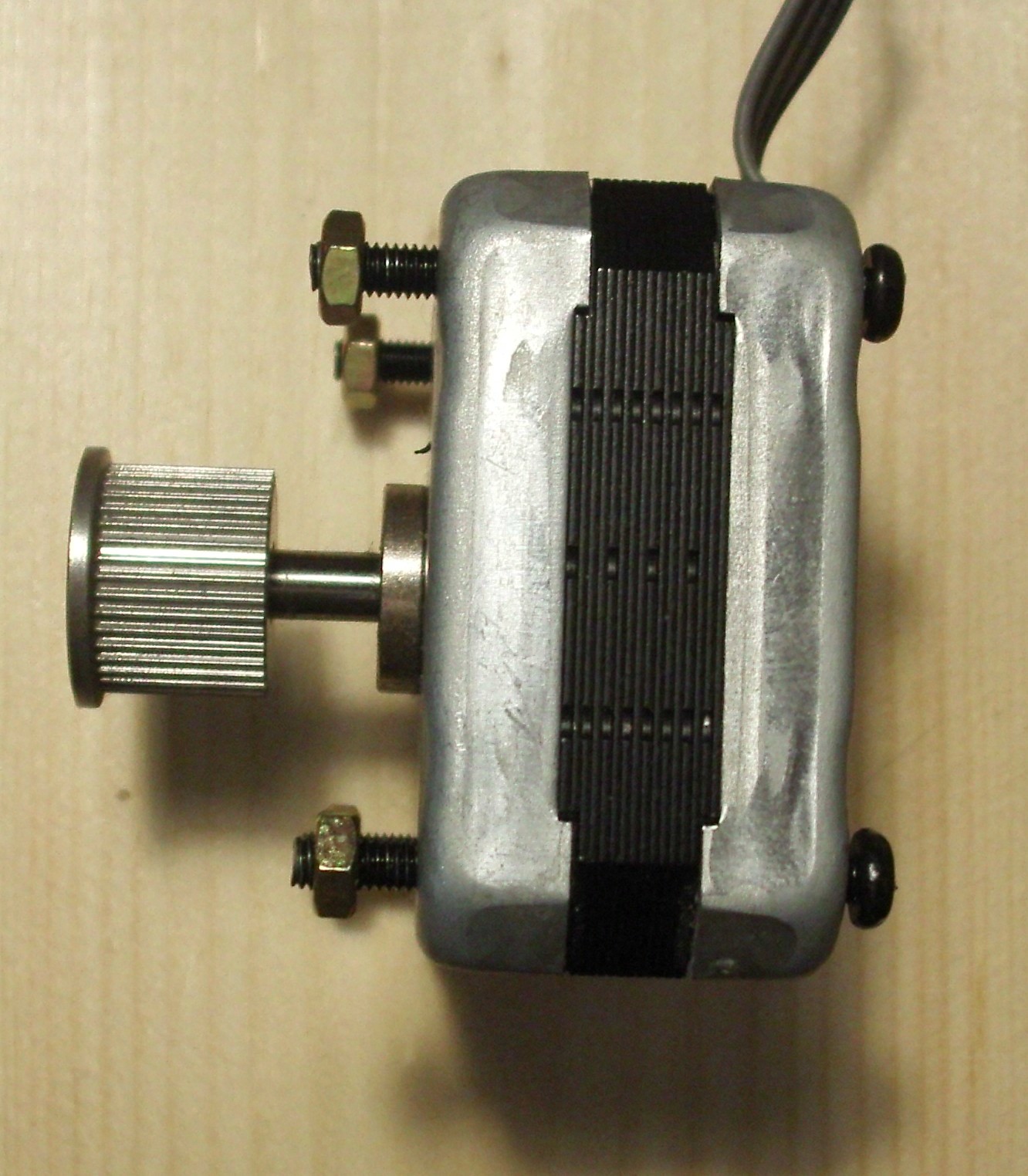
DC motor: While speed/torque can be controlled somewhat by PWM (Pulse Width Modulation, essentially outputting a fractional power, which is close enough to a lower power), they aren't necessarily exacting. They use 1 H-bridge to control. They use a 2 wire connection (Motor input A and Motor input B), from the H-bridge, one of which is providing voltage and the other not. They can be reversed by making the other high. Note that they will never both be high. (Well they shouldn't be anyway.) The example at the left is what you might find in a simple toy, especially like a battery powered fan.
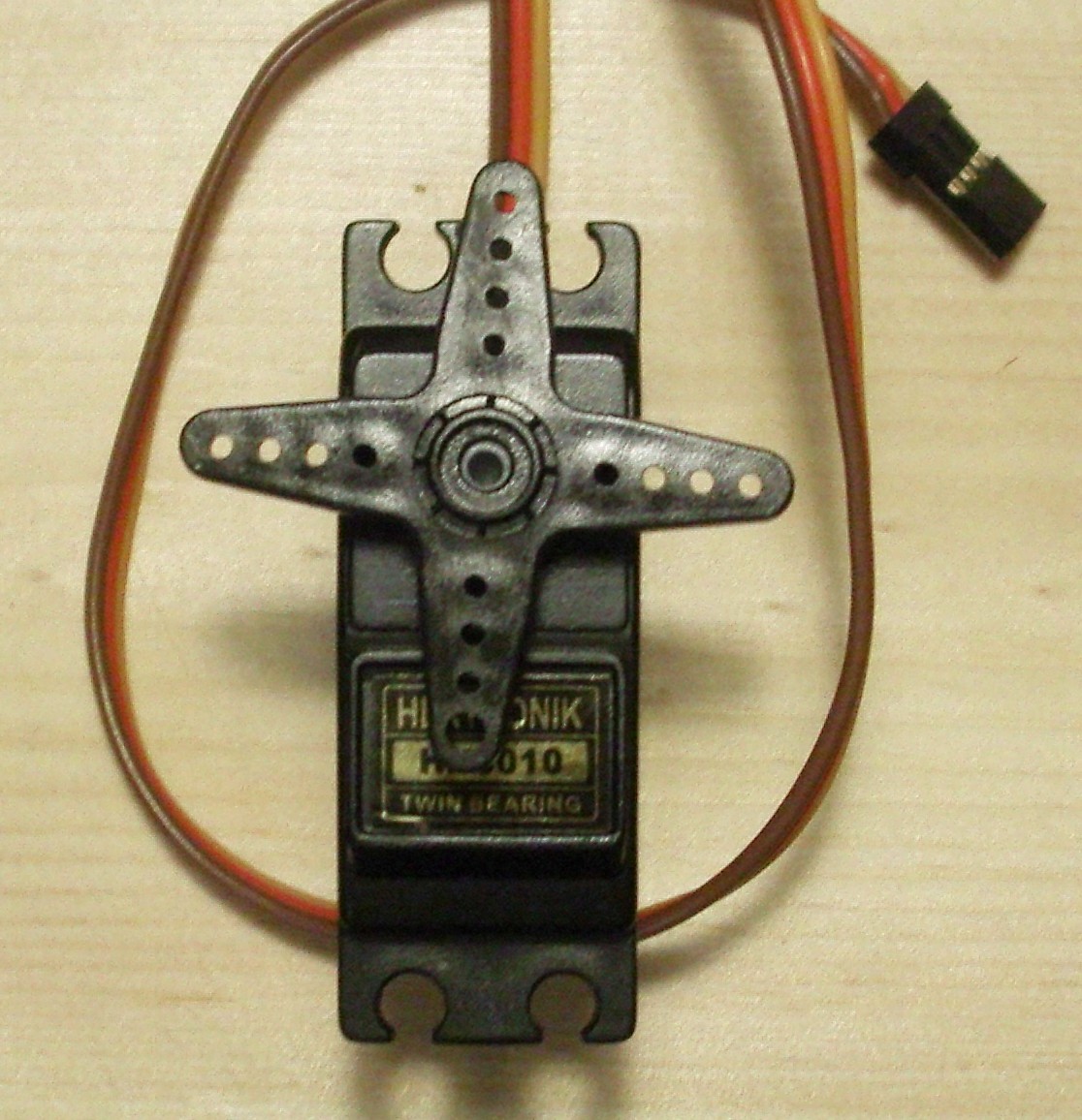
Servo motor: (commonly just Servos) These have positional control, which is easily programmed, however, almost all servos that you can easily find (trust me, I looked) have a range of motion that's usually either 180 or 270 degrees. While this can be translated into larger linear motions, with a large connector, it means it's harder to handle. Internally, they have a DC motor, but also have gears and electronics to have it move/hold position based upon a PWM signal. Requires 1 PWM output to control. They use a 3 pin (Signal (PWM), Vin and GND) connection. The example at the right is what seems to be called a hobby servo.
Continuous Servo Motors: These are servo motors which have been modified, so that the speed is what is controlled. This means that they don't control position. Making them very similar to straight DC motors, but often with higher torque, due to gearing, and finer control. Requires 1 PWM output to control. Like Servos, they use a 3 pin (ground, Vin and GND) connection. I don't have one, so no pictures, but the one above could be modified for continuous rotation, and look exactly the same.Stepper Motors:These motors are very useful for this sort of thing, as instead of controlling speed, they (somewhat like Servos) control position, but don't have a limitation on movement, so they mostly combine the advantages of all of the above, having control over position, having some control over speed, and not being limited in range of motion. How they achieve this is via having (generally) two coils, which alternate which is powered to move, and just keep one on to keep the motor in position. However, they have the drawback in that they require two H-bridges to control. They may use a variety of wires to interface, 4-6 being the most common. In those 4 of them are as far as I can think of always Motor control 1A, 1B (for one coil), Motor control 2A, 2B (for the other). Extra wires are often ground wires. The example on the left is a 7.5 deg/step (48 steps per rotation) from adafruit, which can operate as either unipolar or bipolar (the two types don't make a difference in code, just how they are wired.) The example on the right is a 1.8 deg/step (200 steps per rotation) pulled from an Epson Stylus 777 printer, and will probably be what is used for at least 2 axis of the machine.


There are some variants of the 4, such as linear servos, which control a linear position with the same method a servo maintains it's angle, however, most of them I've come across that are potentially useful for this project, are $100 each, which for my purposes, puts it out of consideration.
Because of the advantages, I decided to go with steppers, I have two 200 steps/rotation (1.8 deg/step) motors I salvaged out of a Epson 777 printer that wasn't working and had been replaced. I also have two 48 step (7.5 degree) steppers, which I will probably end up using for the other axis.
For Arduino, what seems to be the best motor shield is the Adafruit Motor Shield. However, it is insufficient for my choice of stepper motors. It can control 2 steppers (via 2 dual H-bridges), which is very close to what is needed, I was considering using a continuous rotation servo. This left me needing another pair of h-bridges, and considering designs for them. I noticed while looking around, the SOC Cricket, which has 2 H-bridges, and runs Arduino. If you've read the other entries, you'll know I got that. That gives me a total of 6 H-bridges, enough to run 3 stepper motors. (I also have the option to use a few servos as well.)
So electronically, we have the Arduino Duemilanove, Adafruit Motor Shield (hooked to 2 steppers), talking to the Cricket, which will be connected to 1 stepper. (Another post will cover the communication needs of the project). For power, neither the Duemilanove/Motor Shield or the Cricket can use their normal power (5V and 3.3V respectively) to power the motors, so we have to hook up motor power for both of those, separately (though we can probably use the same power source for both motor powers). As far as for the devices themselves, they don't draw much power, so we will be powering the Duemilanove off USB, and the Cricket from the Duemilanove's 3.3V power.
Monday, July 26, 2010
Setting up the Arduino Software to program the Cricket
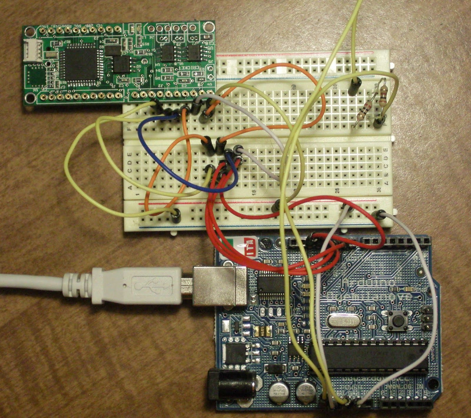 To the left we see the simple circuit to program the Cricket. This is a second breadboarding based upon my last post to make sure it's correct. One thing the shown circuit lacks is the LEDs (and resistors, don't forget them!) hooked up to pins 7-9 to see it the Cricket being programmed by the Duemilanove successfully, but the circuit works. The resistors in the upper right, are to disable auto-reset.
That brings us to Step 2: Getting the Arduino software to work with the Cricket. For this I originally thought that it required modifying a line in the Arduino software itself, fortunately this is not the case, because when tracking the code backwards, I discovered the upload.using parameter of boards.txt, something which controls the list of boards you see in the Arduino program under the Tools menu.
 If you open the Arduino software (I assume you know how to install it for your OS, I found it best to install the packages for Ubuntu, then download the standalone (I actually used svn, as I was looking to patch it for a while.) because we also have to install the Sanguino extension to Arduino. Sanguino is another hardware board similar to the official Arduinos, such as Duemilanove or earlier models, but using the Atmega644P, as opposed to the Atmega8/168/368 series (used in official Arduinos). This is almost what we want, as the differences between the 644 and 644P appear to be negligible, aside from the addition of a second USART in the 644P, and a few power saving changes. Fortunately, even though the Sanguino project uses the 644P, the software extension to Arduino is compatible with the 644. (Provided no bugs exist, and there are always bugs.) The instructions to install Sanguino are on the front page, I'm assuming you can copy a directory, into another.
Now, my image shows an entry for the Cricket. We really want to have that entry, so in the 'Sanguino' directory you just copied, locate the boards.txt file. We need to tell it about the Cricket, this means telling the Arduino software what to use to program it, what speeds, and what fuse settings (those may not be absolutely necessary, but I have not tried them without it.) Add the following to the end of boards.txt, which should have very similar entries, but for Sanguino.whatever. Note, this is for a 10MHz one, for other speeds, you will have to adjust the build.f_cpu frequency setting, and possibly the fuses (these settings come in the download below)
cricket10.name=Cricket 10 MHz (Atmel 644 @ 10 MHz)Then copy the bootloader from the download of Soc-robotic's Chinook firmware bootloaders/atmega644/BootLoader_Cricket_10MHZ.hex (Some of this comes from me looking at this blog entry which focuses on the Wasp, but helped me figure this out for the Cricket. Though, I think the only setting which is the same is the two atmega644 settings.)
cricket10.upload.protocol=arduino cricket10.upload.maximum_size=63488
cricket10.upload.speed=19200 cricket10.upload.using=arduinoisp
cricket10.bootloader.low_fuses=0xEE cricket10.bootloader.high_fuses=0xDC
cricket10.bootloader.extended_fuses=0xFF cricket10.bootloader.path=atmega644
cricket10.bootloader.file=BootLoader_Cricket_10MHZ.hex
cricket10.bootloader.unlock_bits=0x3F cricket10.bootloader.lock_bits=0xCF
cricket10.build.mcu=atmega644 cricket10.build.f_cpu=10000000L
cricket10.build.core=arduino
We should be all set, on the desktop. There's one more piece of software to load, this one is the programmer on the Duemilanove. Start the Arduino software, and check that everying prior works, by going to the Tools->Board menu which looks like the one pictured above, and have entries for "Sanguino", and "Cricket 10MHz (Atmel 644 @ 10 MHz)". If so, you are good to this point. From here, select your Arduino's port and then from the Tools menu, your port. (On Linux this is commonly /dev/ttyUSB0 or /dev/ttyUSB1.)
 Now we need to open the (provided) sketch for using the Arduino as an ISP, so go to File->Examples->ArduinoISP. Now, you need to possibly compile and upload to your Duemilanove. First, from the Sketch menu, click Verify/Compile. In the lower blue bar, it should say "Compiling..." then switch to "Done Compiling." For now, disconnect a pin from the resistors which disable the auto reset. After it does, (if there are no errors, which would be in the form of red text inside the black box) you need to upload it, via File->Upload to I/O board. The blue bar should say "Uploading to I/O board", then "Done Uploading". If it shows no errors, you are ready to move on to uploading to the Cricket. If you connected LEDs to pins 7-9 (don't forget the resistors!), then they should light up then go out in the order 7, 8, 9, with 9 staying lit but sort of pulsing, to show it has uploaded. After this is done, you can reconnect the resistors to disable the autoreset.
Now, go back to the board menu, and select the Cricket entry. For this, we will use the Blink example, and then modify it to make sure it's working (and for a little example of programming.) Go to the File->Examples menu again, this time instead of ArduinoISP, open the Digital folder and find the 'Blink' example. (The example should be at the top.). Now, Repeat the Compile/Upload process (the shortcuts are Ctrl-R for compile, and Ctrl-U for upload). If you connected LEDs, you should see the one connected to 9 remain on (as usual), but also the one connected to pin 7 (programming) light up for a bit. If pin 8's lights up, that indicates an error. (I haven't seen this happen, so my advice would be double check your circuit, and try once again. After that, start googling for the problem, or asking for help.)
Once the programming led goes out, and/or the software says Done uploading, one of the two LEDs should start to blink every second. That's great, but I've noticed the cricket sometimes blinks with whatever bootloader it had. So to make sure we know that it is right, we shall use both LEDs. On the row after to where it says int LedPin = 13;, add the line "int LedPin2 = 12", and replicate each line with LedPin in it, on the line below it, with LedPin2 substituted for LedPin. Then in the loop() function, on the LedPin2 lines, change LOW to HIGH and HIGH to LOW, this will cause the LEDs to alternate, every second. Compile, then upload it again. and the LEDs should start a slow alternation every second. You can also adjust how long each one is on, by changing the number of microseconds in the delay functions, say 100. So change both occurances of 1000 to 100, and Compile/Upload, and the two LEDs should fairly rapidly alternate.
That should be all for now, next post will talk about controlling a DC motor and possibly stepper motors.
Saturday, July 24, 2010
Using Duemilanove to Program the Cricket

As promised, this will have pictures, though not necessarily great ones.
After finding a what seemed like a great deal on ebay, An arduino compatible When I got it I realied that the header to turn the top left port into a 10-pin standard ISP header wasn't included (as my plan was to order a serial port ISP10 programmer), I really wanted to figure out how to make the board useful.
To the left is the Cricket with labels on it, note that my particular one has a Serial flash and a 10MHz crystal. First of all, a general description, I consider this board to be turned 90 degrees clockways from normal orientation. (This was done so most pins can be labeled.) The pins are labeled via Arduino(/Sanguino, I'll get to that later) pinout. For right now, what we want to do is program the chip. The pins we need are marked in the upper left of the image.

Atmega processors are programmed using In-system programming, which normally uses a 6 or 10 pin header carrying the required information. (Though the 10-pin doesn't use all of them.) If you look at the picture of the Arduino Duemilanove, you will see a 6-pin header on the right, this is for ISP programming of the chip. The pin out has a pin for Reset, Serial Clock (SCK), Master to Slave Communication (MOSI), Slave to Master (MISO), a 5V and obviously Ground. The 10-pin adds an LED indicator, and more Ground connections.
Fortunately, Arduino is popular enough that, someone has already written an implementation of ISP programming, which is distributed in the example sketches. Called ArduinoISP, this is usually used to allow uploading just the bootloader to another Arduino, but in this case, due to the lack of USB, and my desire not to splice serial cables, I will be using this to upload sketches as well. You will find that it uses pin 13 for sck, 12 for MISO, 11 for MOSI, and 10 for reset. As well as using 9, 8 and 7 for status LEDs. (Check the file)
 On the cricket, all of these functions are brought out nicely to a header, and the cricket is easily inserted into a breadboard (It's not possible to see, but the cricket is essentially stackable). I use this to make it easy to adjust which pins go where, and to make it easy for future reprogramming, I set it up on a breadboard, such that it is simple to plug the cricket back in. If you look at the first picture, you'll see there are 7 pins contained, in addition to the 4 labeled, they are 2 for power (Vcc and Ground, which in my case, must be a 3.3V, fortunately the Arduino supplies this), and one for SS, which is Slave Select. This needs to be held low, which I noticed, conveniently happens on RESET, as I read the ArduinoISP code, so I'm going to have it also go to SS, as well as reset.
So, the 7 pins, need to be connected to pins 10-13 and power on the Arduino, this is one to one, except for pin 10 to SS as I've used it, SS can also be connected to ground. (That's probably a better solution anyhow. EDIT: Not really, I just tried it and it failed to work, so just use pin 10) On the breadboard, I've connected them to a few rows on the opposite side, matching the Arduino pins, so that I can easily plug wires from the Arduino into the matching number. (I may make a diagram later, as it is counting from the top/left of the cricket's J2 connector, Arduino pin -> Cricket pin: 3.3V -> Vcc; 11 -> 5/MOSI; 13 -> 7/SCK; 10 OR GND -> 4/SS; 12 -> 6/MISO; 10 -> RESET; GND -> Ground)
Now, there is one other issue: Automatic reset. As far as I can tell, this needs to be disabled while using the Arduino as an ISP programmer. There are two ways to disable it. One is to cut a trace, which will disable it until that trace is bridged. Which seems like an annoying case (and if you want to disable it again, cut, etc.) Apparently earlier Arduinos provided a jumper. Unfortunately my Duemilanove doesn't. However, there is a much more elegant solution, which is to temporarily disable it. This is accomplished via a 110 ohm resister between reset and 5v. (In my picture, that's the two resistors in the lower left.)
Now you can try to upload the Cricket bootloader with the avrdude command: avrdude -b 19200 -c arduino -p m644 -U flash:w:BootLoader_Cricket_10MHZ.hex -P /dev/ttyUSB0 if the bootloader (obtainable from soc-robotics) is in the directory. You may also have to adjust the port (-P option). This should upload the bootloader. I believe The LED will slowly flash.
Next post will describe how to upload programs(sketches) to the Cricket and how to set up the Arduino software to handle it, due to the chip being an Atmega 644 and not a normal Arduino chip, and the difficulty of using an ISP programmer for sketches as opposed to using the bootloader. (It might be two parts.)
Oh, and just so it's clear: images in this post Copyright 2010 by James L.
Subscribe to:
Posts (Atom)