As noted in the initial post, I already have some (most) of the electronics required. First of all, some basic ideas of how the project is going to be built.
First of all, this is going to be a three dimensional device, and the cutting head will be able to move on at least 3 axis. This means there will need to be at least 3 motors operating to position it. Below is a small summary of what seem to be the four main ways to move something using a small controller:

DC motor: While speed/torque can be controlled somewhat by PWM (Pulse Width Modulation, essentially outputting a fractional power, which is close enough to a lower power), they aren't necessarily exacting. They use 1 H-bridge to control. They use a 2 wire connection (Motor input A and Motor input B), from the H-bridge, one of which is providing voltage and the other not. They can be reversed by making the other high. Note that they will never both be high. (Well they shouldn't be anyway.) The example at the left is what you might find in a simple toy, especially like a battery powered fan.
Serv
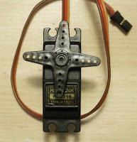
o motor: (commonly just Servos) These have positional control, which is easily programmed, however, almost all servos that you can easily find (trust me, I looked) have a range of motion that's usually either 180 or 270 degrees. While this can be translated into larger linear motions, with a large connector, it means it's harder to handle. Internally, they have a DC motor, but also have gears and electronics to have it move/hold position based upon a PWM signal. Requires 1 PWM output to control. They use a 3 pin (Signal (PWM), Vin and GND) connection. The example at the right is what seems to be called a hobby servo.
Continuous Servo Motors: These are servo motors which have been modified, so that the speed is what is controlled. This means that they don't control position. Making them very similar to straight DC motors, but often with higher torque, due to gearing, and finer control. Requires 1 PWM output to control. Like Servos, they use a 3 pin (ground, Vin and GND) connection. I don't have one, so no pictures, but the one above could be modified for continuous rotation, and look exactly the same.
Stepper Motors:

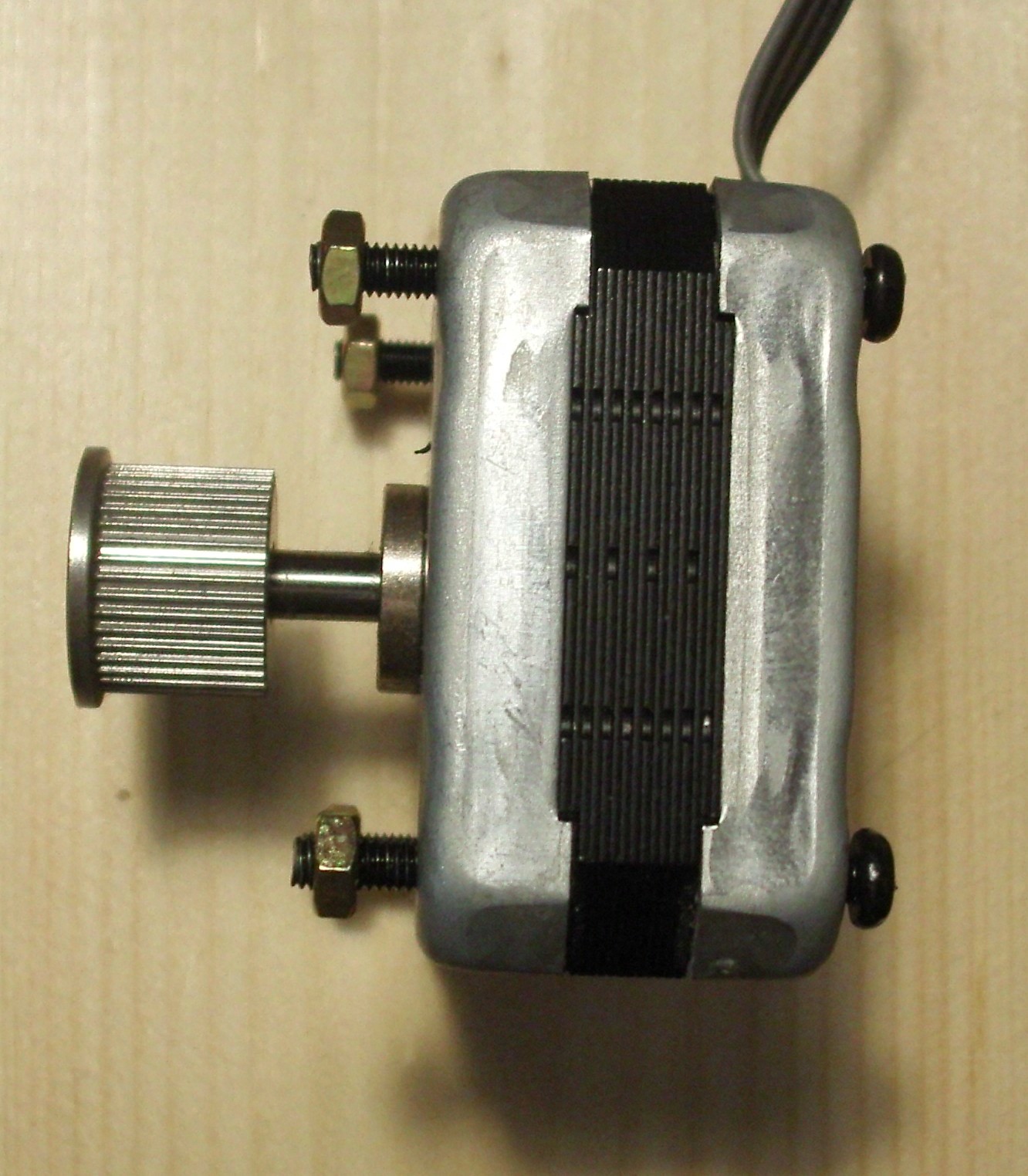
These motors are very useful for this sort of thing, as instead of controlling speed, they (somewhat like Servos) control position, but don't have a limitation on movement, so they mostly combine the advantages of all of the above, having control over position, having some control over speed, and not being limited in range of motion. How they achieve this is via having (generally) two coils, which alternate which is powered to move, and just keep one on to keep the motor in position. However, they have the drawback in that they require two H-bridges to control. They may use a variety of wires to interface, 4-6 being the most common. In those 4 of them are as far as I can think of always Motor control 1A, 1B (for one coil), Motor control 2A, 2B (for the other). Extra wires are often ground wires. The example on the left is a 7.5 deg/step (48 steps per rotation) from adafruit, which can operate as either unipolar or bipolar (the two types don't make a difference in code, just how they are wired.) The example on the right is a 1.8 deg/step (200 steps per rotation) pulled from an Epson Stylus 777 printer, and will probably be what is used for at least 2 axis of the machine.
There are some variants of the 4, such as linear servos, which control a linear position with the same method a servo maintains it's angle, however, most of them I've come across that are potentially useful for this project, are $100 each, which for my purposes, puts it out of consideration.
Because of the advantages, I decided to go with steppers, I have two 200 steps/rotation (1.8 deg/step) motors I salvaged out of a Epson 777 printer that wasn't working and had been replaced. I also have two 48 step (7.5 degree) steppers, which I will probably end up using for the other axis.
For Arduino, what seems to be the best motor shield is the Adafruit Motor Shield. However, it is insufficient for my choice of stepper motors. It can control 2 steppers (via 2 dual H-bridges), which is very close to what is needed, I was considering using a continuous rotation servo. This left me needing another pair of h-bridges, and considering designs for them. I noticed while looking around, the SOC Cricket, which has 2 H-bridges, and runs Arduino. If you've read the other entries, you'll know I got that. That gives me a total of 6 H-bridges, enough to run 3 stepper motors. (I also have the option to use a few servos as well.)
So electronically, we have the Arduino Duemilanove, Adafruit Motor Shield (hooked to 2 steppers), talking to the Cricket, which will be connected to 1 stepper. (Another post will cover the communication needs of the project). For power, neither the Duemilanove/Motor Shield or the Cricket can use their normal power (5V and 3.3V respectively) to power the motors, so we have to hook up motor power for both of those, separately (though we can probably use the same power source for both motor powers). As far as for the devices themselves, they don't draw much power, so we will be powering the Duemilanove off USB, and the Cricket from the Duemilanove's 3.3V power.

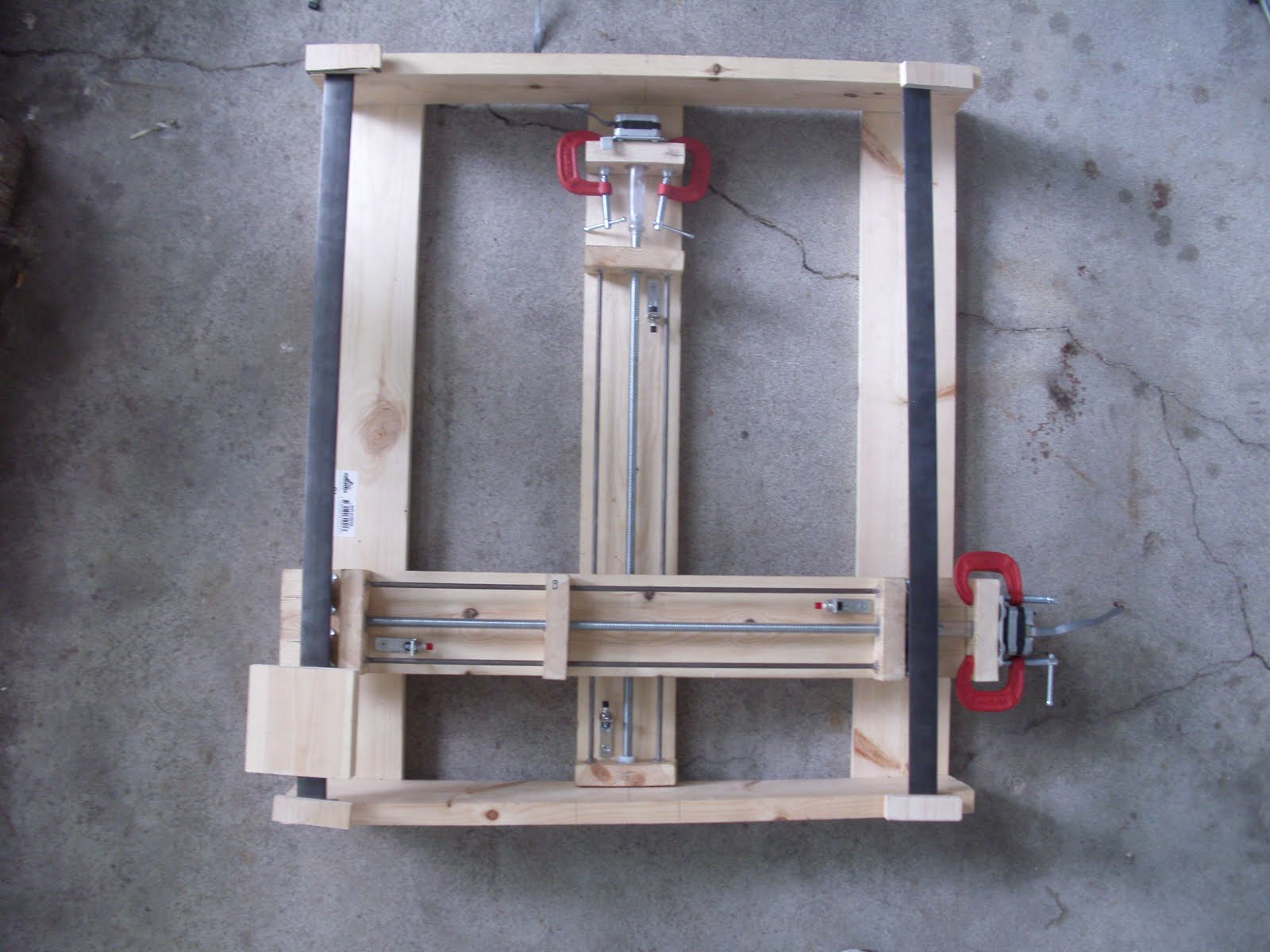
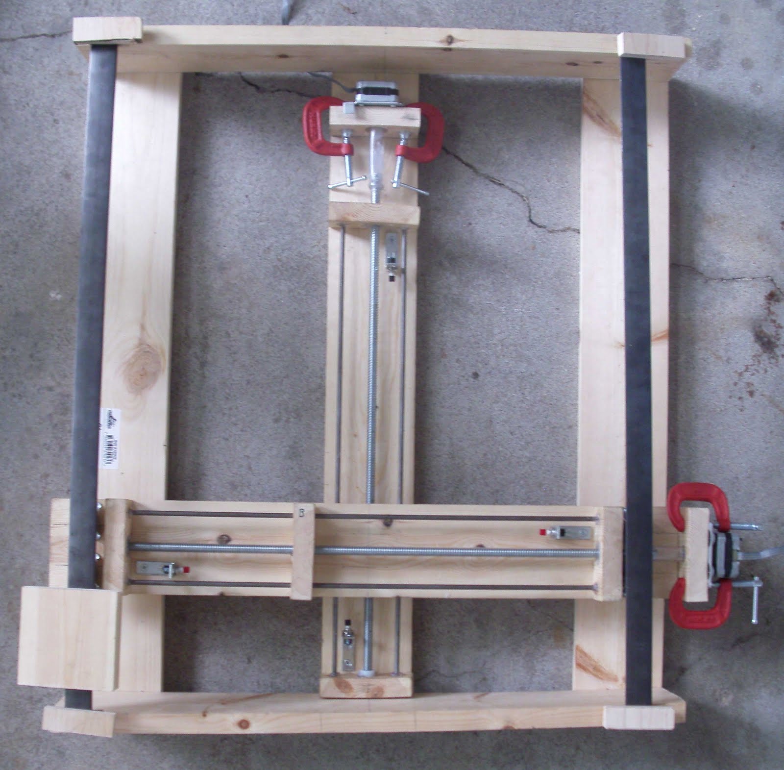 Have a picture of the x/y assembly! It is upside down, and the rails aren't attached yet. You can see some of the odd things I've used, such as the mini clamps to secure the motors, and the vinyl motor to shaft connectors. The block in the lower left was just sitting there to hold the rail down, because the concrete was uneven. The limit switches are in their brackets (easily removable), but I have to adjust the brackets some: the ones in the x/upper, but lower in the picture are too tall, given a mistake I made, so I have to cut the tops off, or grind the top hole out in the L-bracket. (It's just a *tiny* bit too small as it came.) You can also see most of that in the little picture up at the right.