For Stepper motor controlled axis, you need to have some sort of sensor to tell when you've gone too far, and to figure out where you are.
There two options that seem somewhat practical, there are also some solutions like laser positioning, which seems expensive, complicated and impractical:
1) Rotary encoders, which don't completely show you where you are (I don't think), but they also let you know if you didn't step, because the motor stalled. (A possibility which can burn out chips.) These generally are used on conventional motors, not steppers, but can be to make sure that it steps on better equipment.
2) Limit switches, which tell you where the limits of motion are, and combined with a stepper, assuming it doesn't stall should tell you the position. Also much cheaper. Ideally, these should have very little resistance.

I opted for Limit switches, though mine don't have quite the limited resistance that one would like. My solution was probably a bit unconventional, but what's new. It's probably what you get when you have someone with no formal training in any circuitry, woodworking, machining, and little formal programming training. In fact, this whole project has that fun of learning while I go. (That fun can also be very frustrating.) To calibrate exactly where one is, it has the problem of having to go to the edge to set the position. I plan on storing the position when it's turned off into the eeprom.

My solution was to take some L-brackets (Basically pieces of metal bent into 90 degrees, with 4 holes for screws.) and then put some momentary switches from radioshack into it. Unfortunately, the holes in the L-brackets were just a bit too small. Well, that was solved via an application of remel grinding them out a bit. It's not absolutely perfect, as due to my mistake on the x-axis of putting the middle bit upside down, the 1-1/2 inch ones are just a bit too tall, so I'm going to have to cut them down, or Dremel out and use the top hole on the perpendicular unscrewed part. Cutting it will be easier, so that's what I'll do. This may not be the best solution, as the switch may not trigger at the same place every time, due to more resistance than others. Also, it might be better to go with normally closed switches instead of the normally open ones I got, so that it will cut out if a connection is broken, or anything else fails.

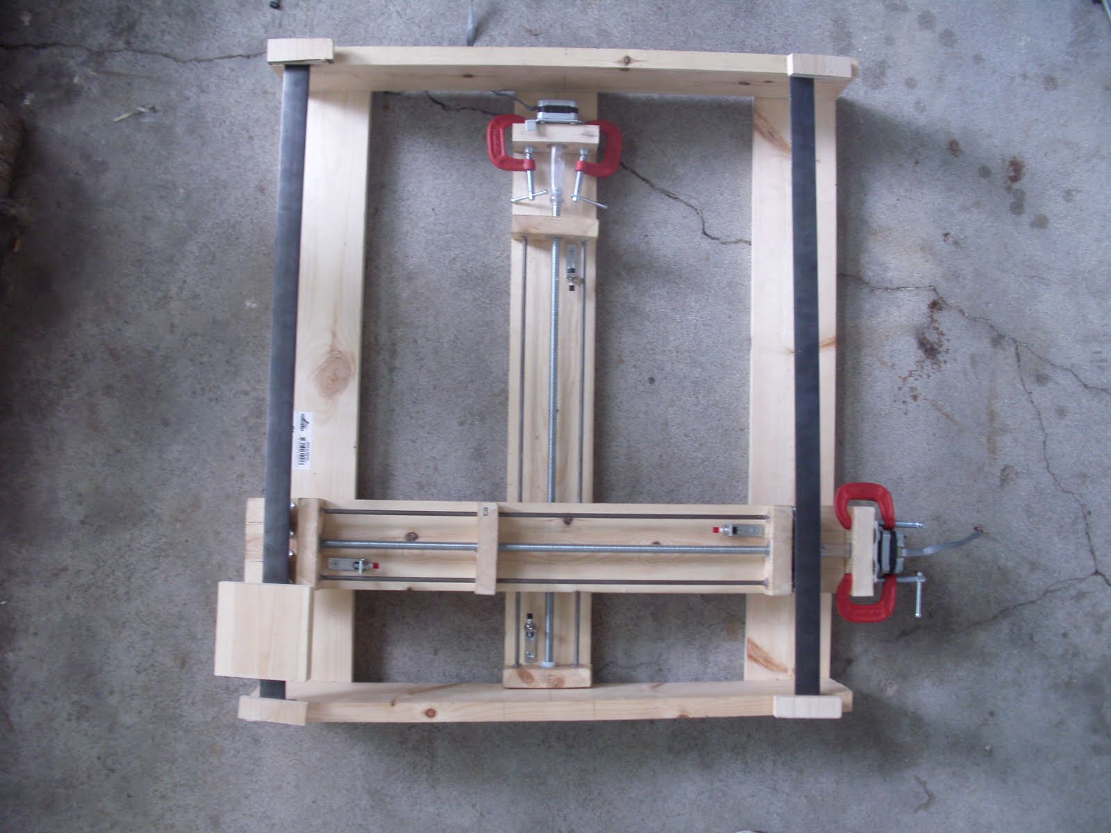
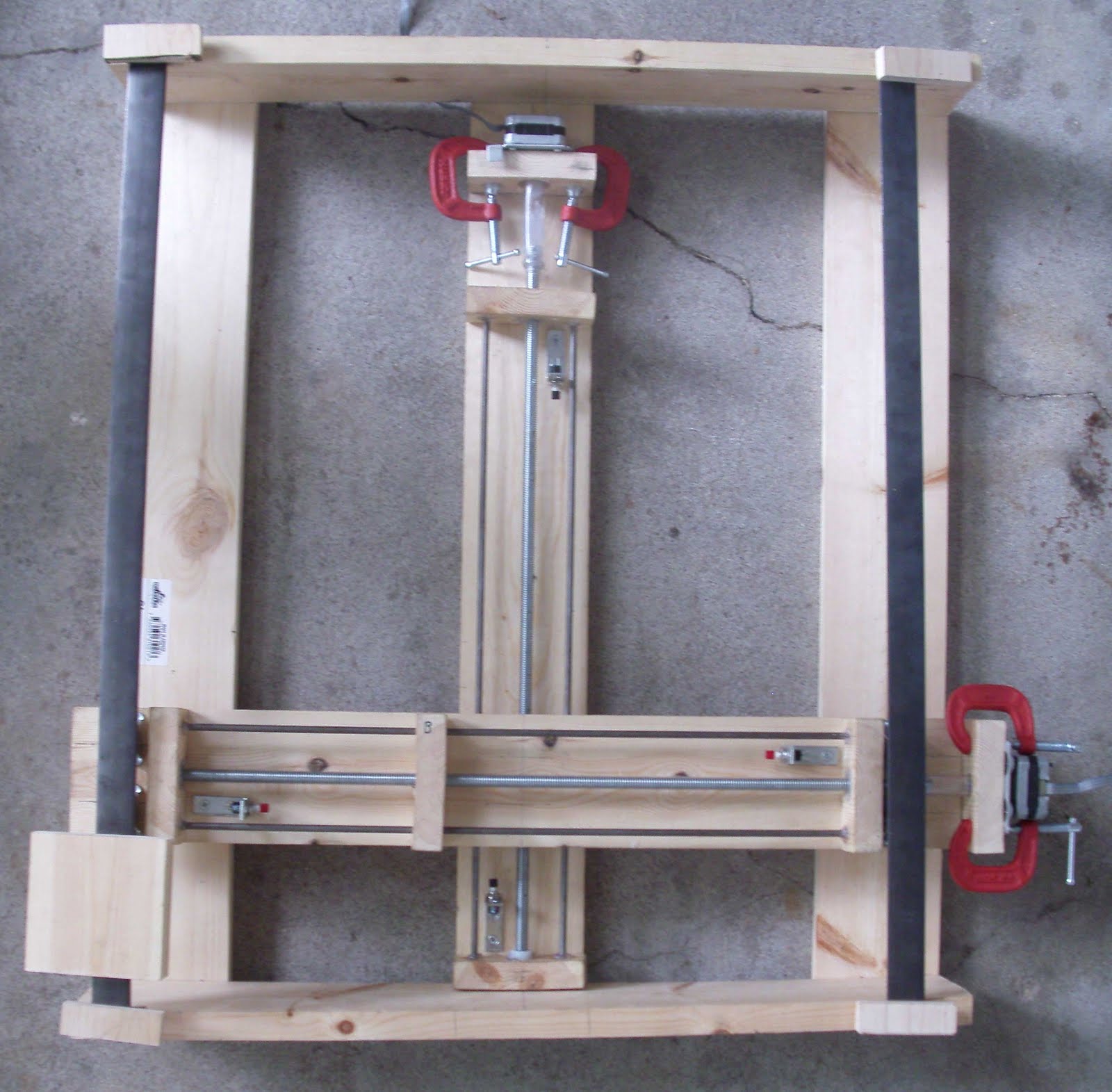 Have a picture of the x/y assembly! It is upside down, and the rails aren't attached yet. You can see some of the odd things I've used, such as the mini clamps to secure the motors, and the vinyl motor to shaft connectors. The block in the lower left was just sitting there to hold the rail down, because the concrete was uneven. The limit switches are in their brackets (easily removable), but I have to adjust the brackets some: the ones in the x/upper, but lower in the picture are too tall, given a mistake I made, so I have to cut the tops off, or grind the top hole out in the L-bracket. (It's just a *tiny* bit too small as it came.) You can also see most of that in the little picture up at the right.